Cleaning the tracks of a garden railway is a long and tedious task and it is interesting to drive trains by radio by inserting a battery and radio equipment in the locomotive or in a wagon behind the locomotive.
Generally the radio systems for the model railways are identical to those of radio controlled cars or airplanes. These systems work well but do not allow sound system and control of multiple locos on the same layout is not simple. Each loco needs a dedicated radio control.
So I asked myself the question whether it was possible to transmit the DCC signal by radio in order to have all the advantages of DCC (sound system, steering more locos) without passing the signal through the tracks. Well, the answer is yes. This is possible with a reasonable cost approximately 100 Euros for the radio system and batteries to be added to the price of DCC decoder.
1. System Description
The system uses components provided for transmitting an audio signal. Indeed, a DCC signal uses a frequency of 8 kHz for the transmission of bits to 1 and the signal spectrum is included in the spectrum of an audio signal (20 Hz - 20 kHz). It is therefore possible to use audio equipment to transmit a DCC signal. For example, it has already been shown that it is possible to use an audio amplifier as a DCC booster.
For radio transmission, there are commercially available modules for transmitting an audio signal at frequencies of 433 MHz and 2.4 GHz. For my system I chose 433 MHz AUREL modules.
2. Radio DCC transmitter
The transmitter consists of a 433 MHZ AUREL radio module called "FM TX AUDIO". This module is supplied with 9 V. It receives an audio signal of about 200 mV input and delivers the modulated FM carrier. This module is available from CONRAD at a price of 25 Euros.
You must add a small antenna at 433 MHz.
It is obviously necessary to insert an attenuator between the DCC booster output and AUREL module input. You can use any DCC booster or you generate the DCC signal on the parallel interface of a PC.
For the first tests, I tested the two foffowing solutions for generate the DCC signal
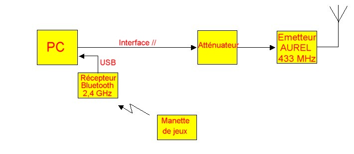
- creation of the DCC signal by the PC parallel interface.
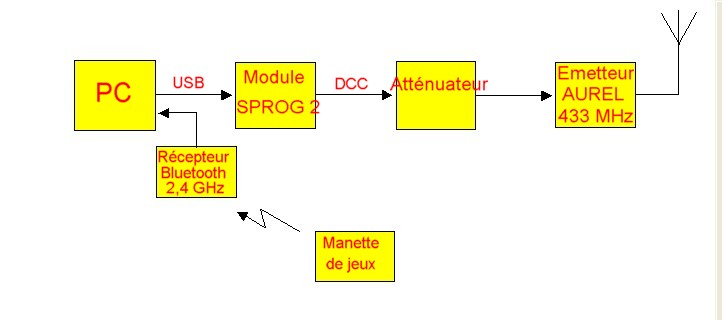
- Using a Sprog 2 module interfaced with the PC via USB.
The first option is cheaper but will soon be obsolete because new PCs no longer have a parallel interface.
The diagram for the first solution is shown in figure below
The diagram for the second solution with Sprog 2 is shown in figure below.
Trains can be controlled using the keyboard and mouse of the PC, but it is also possible to use a wireless joystick. So everything goes on the radio.
The PC acts as a relay between the wireless joystick and trains. The joystick can control several trains. The number of trains on the layout is not limited since the DCC radio signal is received simultaneously by all trains.
3. Radio DCC receiver
3.1 System description
The locomotive must be able to move from DCC provided either by track or by radio. The choice is made by a switch under the locomotive.
Accordingly, the DCC decoder and speaker are installed in the locomotive.
The radio equipments and batteries are placed in a wagon which provides the DCC signal to the locomotive.
These equipment includes:
- 433 MHZ FM AUREL radio receiver called "RX FM AUDIO"
- DCC booster that amplifies the signal provided by the radio receiver.
- power supply that is provided by two Li-ON Canon batteries (BP ref 511) with a voltage of 7.4 volts each.
- A fuse battery (Li-On batteries should never be short-circuited because they can ignite and explode)
- A voltage regulator that supplies the voltage of 3 volts to the radio receiver.
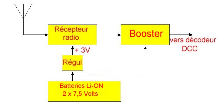
The figure below shows the interconnection of equipment to be installed in a wagon.
3.2 Choice of batteries
I chose Li-On Camcorder batteries. They have a good relationship between energy and weight.
Every Canon BP-511 battery has the following characteristics:
Capacity: 1500 mAh
Voltage: 7.4 V
Length: 55 mm
Height: 21 mm
Width: 38 mm
Weight: 76 g
This battery is available from aboutbatteries.com priced at 15 Euros. It should also have a charger (price 28 Euros). 3.3 Booster description
3.3.1 A few technical
The booster must provide a minimum voltage of 10 volts RMS to the DCC decoder, which corresponds to a voltage of 28 volts peak to peak. With a conventional booster using a single operational amplifier, we must have a power supply of 28 volts.
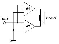
The use of a bridge circuit with two operational amplifiers allows to divide by 2 the supply voltage. You can then use two power supplies from 7 volts only. The principle is illustrated in Figure below.
The two identical amplifiers A1 and A2 are connected in bridge configuration. If one amplifier is capable of producing ± 10 V relative to ground (20 Vp-p), the second amplifier will output the same signal, but inverted. If the load is connected between the outputs of the two amplifiers (instead of a link between output and ground), you can get up to 10 V - (-10 V) = ± 20 V (or 40 V peak-to-peak) total, which is double of what each individual amplifier can provide.
3.3.2 Using an audio amplifier as a booster
It is quite possible to use an audio amplifier as a booster amplifier provided that the installation uses a "bridge". To provide an output voltage of 12 Vrms at DCC decoder, the audio amplifier used as a booster should be able to provide in a load of 8 Ohms 18 Watts of power (P = V2 / R).
I tested two amplfiers that have worked well and can be used as a DCC booster
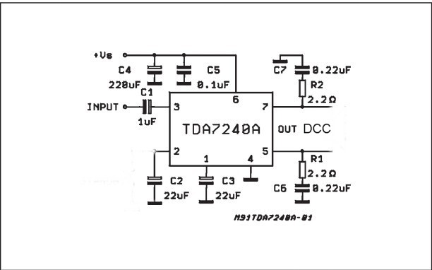
Booster made from an audio amplifier TDA 7240.
The circuit TDA 7240 is a bridge amplifier that can deliver a power of 20 Watts in 8 Ohms with a power of 15 volts.
The diagram is given in the figure below.
You can build yourself a printed circuit board, but you can also buy the 12 µP kit at Microprocessor at a price of 14 Euros.
This kit is complete with a preamplifier. It is not necessary to wire the complete kit. Just wire the TDA 7240 and the components described in the figure above. Do not forget to set the TDA 7240 on a radiator.
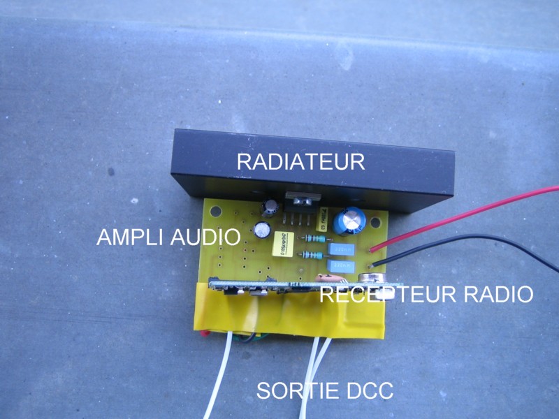
The figure below shows the radio receiver and audio amplifier connected together. The small size (70x40x40 mm) allows to insert it in a wagon behind the locomotive.
With a power supply of 15 volts, the circuit can provide an RMS voltage of 12 volts to a DCC decoder. The maximum current is about 1 A.
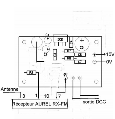
The figure below shows the wiring of the components on the PCB kit µP12 with connections to the radio receiver AUREL TX-FM.
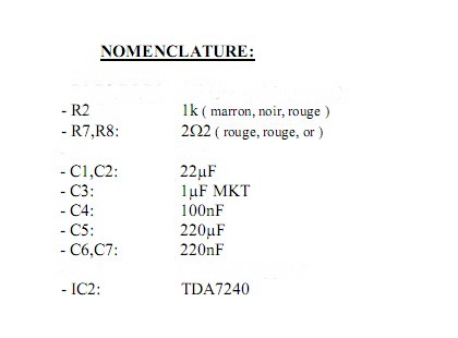
The nomenclature of the components to be welded on the PCB is as follows.
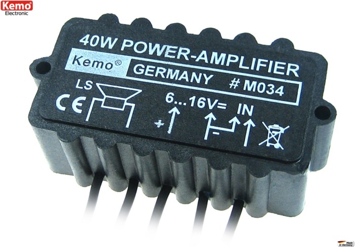
Booster made from a KEMO amplifier.
The previous circuit works very well, but the maximum current is limited to about 1 A. Some engines require a higher current, up to 2A. So I tried an amplifier compatible with this requirement.
My choice was a 40 W KEMO amplifier [M034] purchased from Conrad who can provide a power of 40 Watts into a 4 ohm load. Its dimensions (69 x 35 x 23 mm) allow for easy insertion into a G scale wagon.
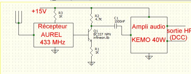
This amplifier requires an input voltage greater than 200 mVrms. The Aurel module delivers only 100 mV. It is therefore necessary to place a preamplifier between the Aurel module and the amplifier. This preamplifier is very simple. It consists of a transistor BC 337, two resistors and a capacitor. The complete diagram of the receiver is given in figure below.
4. List of components
You can download the list of components and suppliers and prices by clicking here.
5.
The first tests with a G scale Billard railcar
The first tests were performed with a Billard railcar already equipped with a DCC decoder ESU LokSound XL. The only change on the railcar was to install a socket for receiving the DCC signal and a switch that lets you choose the outlet by track or by radio.
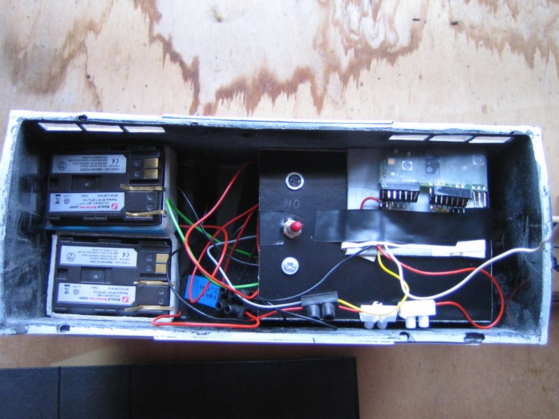
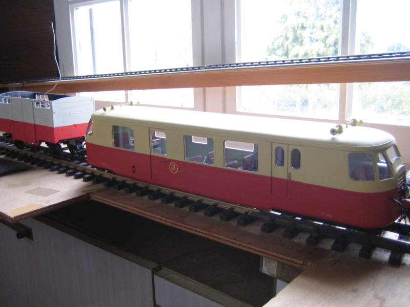
Radio equipment was installed in a trailer as you can see in the picture below.
You can see on the left the two Li-On batteries and the fuse. At right is the radio receiver AUREL at 433 MHz. The booster is under the black card on the right.
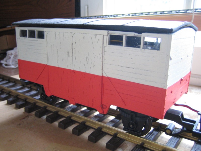
And a photo of the railcar coupled to the trailer.
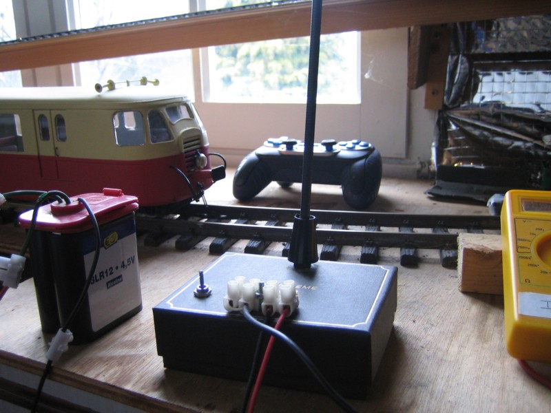
The photo below shows the 433 MHz radio transmitter and antenna.
And here's a video that shows the tests on the garden railway where the rails have not been cleaned since last year.